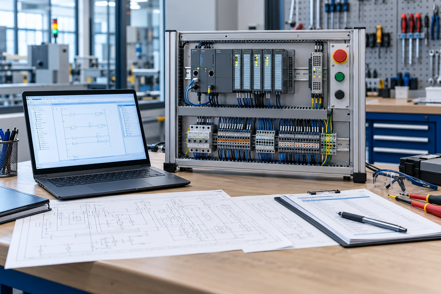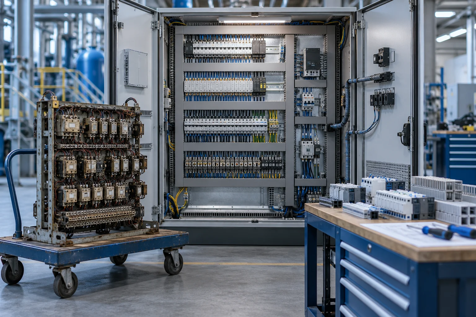
A control-panel retrofit involves more than replacing old components with new ones. Wiring, protection, thermal conditions, documentation and actual machine functions must be assessed together. A tidy-looking panel may be technically incorrect, while an old-looking one may still perform some functions correctly. Decisions should be based on measurements and a site survey.
011. Document the as-installed condition
Compare the existing electrical schematics with the actual wiring. Identify relays added later, disconnected sensors and unlabelled cables. Record equipment labels, terminals, I/O mapping and network connections. Complete photographs and a verified connection list before dismantling.
Back up the PLC, HMI and drives separately wherever possible. In addition to a loadable file, obtain the source project, version details and parameters. Losing an undocumented function during a retrofit can halt production even if the new hardware is sound.
022. Reassess protection and power distribution
Review the new equipment's current demand, short-circuit and overload protection, supply arrangement and relevant product instructions together. The fact that an existing fuse is still physically installed does not make it suitable for the new load. Cable sizing, connections and protection coordination are part of competent design.
Normal control, emergency stopping and energy isolation for maintenance serve different purposes. Installing a new PLC does not automatically renew the safety functions. Assess the retrofit's impact on safety and compliance separately. This article does not provide a sizing recipe for any protective device.
033. Plan wiring and electromagnetic compatibility
Route power, drive-output, analogue measurement and communication cables according to their functions. Document how cable shields connect to the chassis and how PE connections are made. Adding cable trunking alone may not resolve incorrect coupling or reference arrangements.
Labels must be durable and consistent with the schematics. Allow access to measurement points needed during maintenance, and avoid overcrowding terminals. Reserve spare trunking capacity and space according to the additions expected in future. Excess empty space should not be confused with necessary maintenance access.
044. Account for thermal and environmental conditions
A new drive or power supply may change the panel's heat dissipation. Compare operating temperatures with the equipment's installation and rating requirements. Select fans, filters or cooling units according to ambient temperature, contamination and the required protection level. Avoid layouts that obstruct internal air circulation.
| Retrofit item | Verification before acceptance |
|---|---|
| Power supply | Stability and capacity under the actual load |
| I/O | Mapping physical points to software |
| Drive | Parameters, direction, reference and stopping |
| Network | Addressing, topology and communication-loss behaviour |
| Heat | Temperature and airflow under a representative load |
055. Document the changeover and rollback scenarios
Define the tasks to be completed during the planned shutdown, the test sequence and the responsible people. Prepare critical materials and spares in advance. A model incompatibility discovered before completion can affect the entire schedule; perform preliminary tests in the workshop wherever possible.
For example, when converting a drive to network control, test the control word, speed units, fault feedback and restart conditions in advance. “Ethernet connection established” is not sufficient for acceptance. Explicitly assess whether reverting to the old arrangement is genuinely possible in terms of both wiring and software if the changeover fails.
066. Complete the final checks against machine functions
De-energised checks and the necessary electrical verification must be performed by competent personnel using the relevant procedures. Then test I/O, manual functions and the automatic cycle in a controlled sequence. Include scenarios such as sensor loss, communication interruption and restoration of power. Production testing may require different product and load conditions.
The handover package should include up-to-date schematics, an equipment list, backups, parameters and test records. Looking tidy in a photograph is only one outcome of a retrofit. The main deliverable is a control system that can be operated safely, understood and restored consistently during future maintenance.
07Example verification scenario
Suppose a sensor is displayed with the opposite state on the HMI after a retrofit. First compare the field device's normal state, input wiring and software logic together. Distinguish the electrical NO/NC arrangement from the state the application regards as correct. Simply reversing the colour of an on-screen symbol may conceal an incorrect cycle condition. Record both the physical state and software result in the I/O acceptance checklist, then retest the associated alarms and interlocks.
Technical references and further reading
For product- and version-specific values, the relevant manufacturer's current documentation should be taken as the reference. The calculations and scenarios above are engineering examples for illustrative purposes.