Adding an emergency stop button to a machine does not complete its safety design. How the hazard arises, when a person is exposed to it and what happens if the protective function fails must all be assessed together. This article explains the basic concepts; it is not a substitute for the risk assessment, circuit design or conformity verification of a specific machine.
01The starting point is the risk assessment
Setting, cleaning, tool changing, troubleshooting and maintenance operations are examined as well as the machine's normal production. Hazards are not limited to electricity: crushing, cutting, hot surfaces, pressure and stored mechanical energy can all exist in the same system. User tasks and reasonably foreseeable misuse must be taken into account.
Risk reduction first assesses the possibilities for reducing the hazard through design; suitable guards and protective functions are then addressed. Instructions for use and warning signs are not an automatic alternative to feasible engineering measures. Every safeguard must be linked to a defined hazard and operating scenario.
02A safety function is not the name of a component
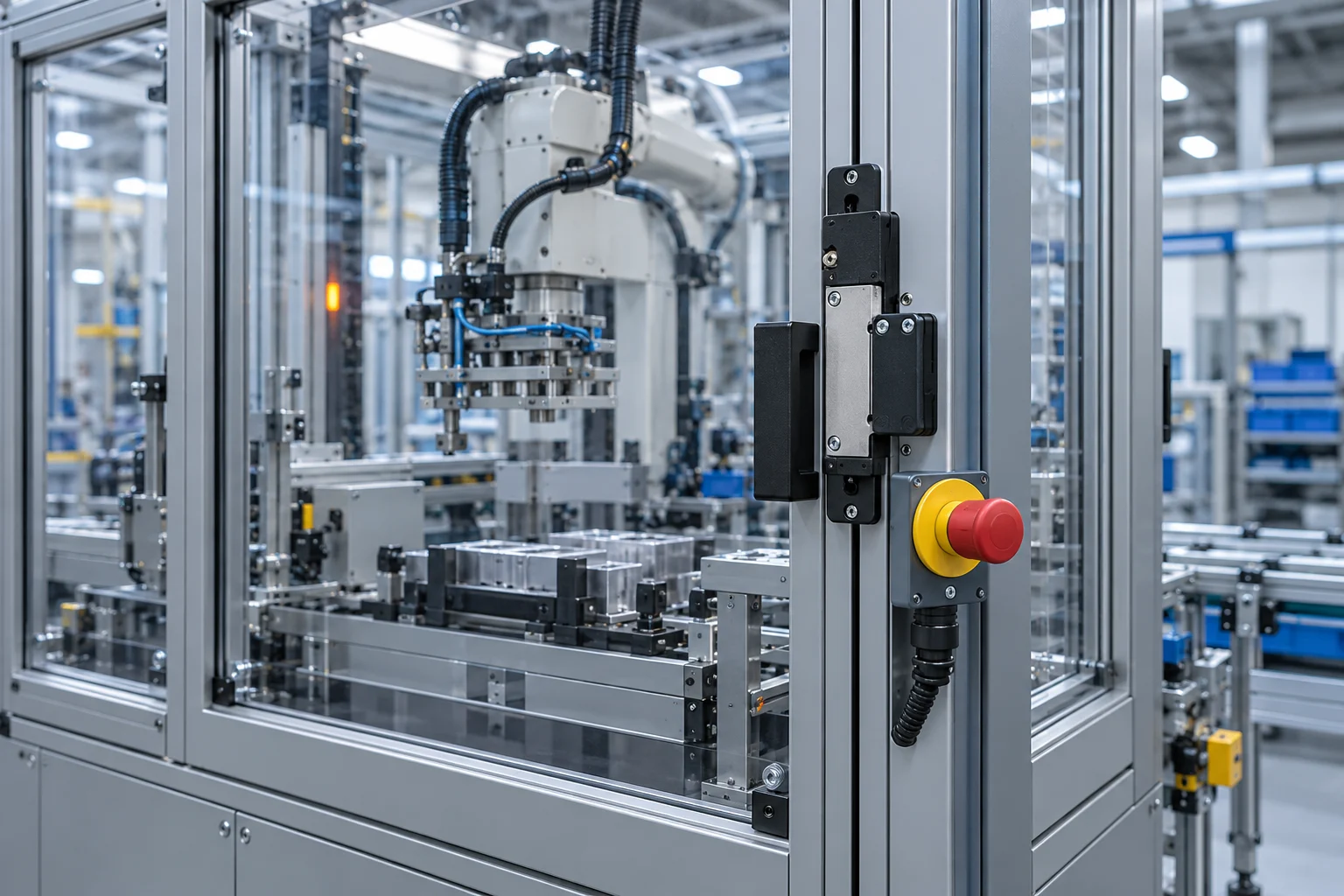
Saying “there is a safety relay” does not explain which safety function the system performs. For example, appropriately stopping a hazardous movement when a guard door is opened can be defined as a function. Its detecting sensor, logic section, final element that cuts power or controls the motion, and feedback are considered together.
Equally, the response time is not just the relay's catalogue time. The sensor, the logic, the drive/actuator and the mechanical stopping time are all part of the chain. Guard placement and the safety distance calculation may depend on this real behaviour. This calculation requires competent design and verification.
03Do not confuse PLr with the PL achieved
The required performance level expresses the need arising from the risk assessment. The level achieved by the implemented control structure, by contrast, is assessed using factors such as component reliability, architecture, diagnostics and measures against common cause failures. A single product marked with a particular level does not by itself prove that the entire chain achieves that level.
| Concept | Question it answers |
|---|---|
| Safety function | Which behaviour must be provided for which hazard? |
| PLr | What level of risk reduction is required for this function? |
| Architecture | How will faults be detected and managed? |
| Verification | Is the design consistent with the requirements? |
| Validation | Does the installed system actually perform the expected function? |
Standards such as ISO 12100, ISO 13849 and IEC 62061 are among the relevant assessment frameworks. Which edition and which application-specific standard applies must be confirmed during the project. No conclusion about the conformity of a circuit can be drawn directly from the general concepts given here.
04An emergency stop does not replace normal safeguarding
An emergency stop is a complementary protective measure; it should not be used as the primary solution for routine access to a hazard. Normal stopping, emergency stopping and energy isolation for maintenance serve different purposes. Pressing the emergency stop does not mean that all energy sources have been safely isolated.
Releasing or resetting the button must not cause a hazardous movement to start by itself either. Restart conditions and the area visible to the operator are assessed in the design. Bypassing a door switch or suppressing a safety fault in software must never be regarded as a fault fix.
05Is it enough to monitor the safety input in a standard PLC?
A standard PLC can monitor the state of the safety chain for production and HMI purposes. However, this monitoring does not remove the requirement for the safety function to be implemented with appropriate hardware and software. Within the same physical system, the responsibilities of standard control and safety control must be clearly separated.
In an example door scenario, the “door open” indication appearing on screen and the hazardous movement being reliably prevented are not the same test. Both outcomes are verified; one is not accepted in place of the other. Situations such as a welded final element or differing types of energy are examined separately.
06What evidence should be provided at handover?
The risk assessment, safety requirements, architecture and calculations, wiring documentation and test records must be consistent with one another. The fault conditions tested for each function and the restart behaviour are recorded. Periodic inspection and maintenance requirements are handed over to the plant.
When the machine is modified, these records are reassessed. A new station or a different stopping time can change the earlier safety assumptions. Safety is not a one-off product purchase; it is an engineering process sustained through design, installation, verification and operation.
07Example verification scenario
Consider a station where motion is expected to stop when a guard door is opened. The acceptance record does not simply state that the motor stops when the door is opened. Which movements are affected, the stopping time, the restart conditions and the defined fault scenarios are also assessed. Residual energy sources, such as pressurised parts or parts that could fall, are examined separately. Validation is linked to the operating and maintenance scenarios specified in the risk assessment; a few successful normal trials do not count as proof of safety for the whole system.
Technical references and further reading
For product- and version-specific values, the relevant manufacturer's current documentation should be taken as the reference. The calculations and scenarios above are engineering examples for illustrative purposes.