An analogue value fluctuating when a motor runs, intermittent loss of encoder pulses or communication failures under particular loads can indicate electromagnetic interaction. Saying “poor grounding” alone is not a diagnosis, however. Identify the coupling path: conduction, common impedance, capacitive coupling and inductive coupling may require different measures.
01Protective earth and signal reference serve different purposes
Protective earthing is part of personnel safety and the protective arrangement under fault conditions. Signal reference defines the electrical relationships used for measurement and communication. Assess where chassis, shield and electronic reference connect according to the equipment design and installation instructions. Never remove protective earth to eliminate interference.
Even if disconnecting a device's PE reduces the symptom, it is not a safe solution. Investigate potential differences, shield currents and connection impedance using suitable measurement and design methods. Resolve the problem without weakening protective functions.
02Cable segregation is a physical design decision
Interaction can increase when drive-to-motor cables, switched power lines and sensitive sensor cables share a long route. Consider separate trunking, suitable spacing, partitions where necessary and appropriate crossings. Use equipment/installation guidance and the electromagnetic environment rather than one universal separation distance.
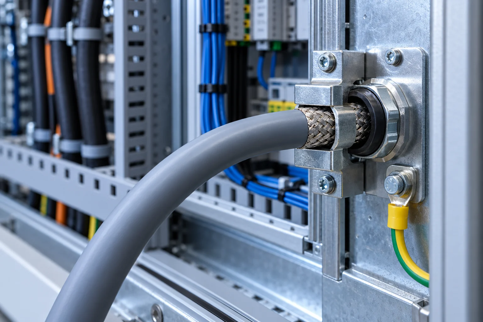
How a cable is terminated matters as much as selecting the correct cable type. Stripping a shield and connecting it to the chassis through a long, thin wire can weaken the expected low-impedance connection, particularly at high frequencies. Depending on the application, a suitable shield clamp and broad contact area can provide a better termination.
03Should the shield connect at one end or both?
There is no single answer for every system. Assess frequency content, cable length, potential difference between endpoints and the manufacturer's shielding arrangement together. Sensitive low-frequency analogue signals may have different requirements from high-speed drive/encoder links.
Follow the equipment documentation rather than a blanket rule that shields must always be connected at one end or always at both ends. Distinguish equipotential bonding from the cable shield's function. A cable shield must not replace a protective conductor unless specifically designed and suitable for that purpose.
| Symptom | First diagnostic question |
|---|---|
| Analogue spike during motor startup | Supply / reference change or cable coupling? |
| Encoder loss at a particular speed | Cable, termination, input filter or signal level? |
| Increasing RS-485 error rate | Common-mode effects, topology or shield connections? |
| Random resets | Have supply transients and the reset line been recorded? |
04Measure synchronously with the event
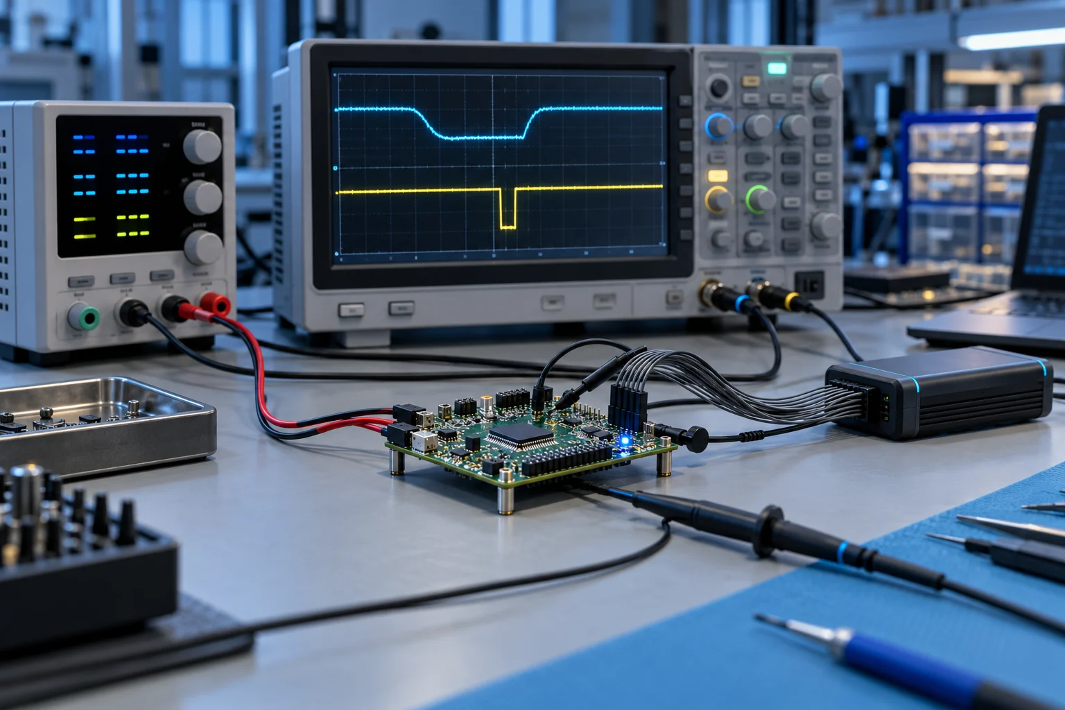
A steady-state DC measurement may not reveal a millisecond transient. Record the relationship between load and the time of the fault. Triggering a suitable recorder or oscilloscope on the event allows the supply, reference and signal to be examined together. The method must suit the circuit voltage and safety conditions.
If a sensor signal is corrupted only while a motor runs, the first test should compare the supply and raw measurement over the same period, rather than add filters at random. Interference may originate in the analogue front end; increased averaging in the HMI may merely smooth the display. Changes made without recording this distinction complicate diagnosis.
05Test one variable at a time
Changing the cable route, shield connection, filter and supply simultaneously makes it impossible to identify which measure helped. Proceed in a controlled sequence wherever possible. Record the symptom, test conditions and result at each stage. Temporary test connections must not replace a permanent, documented installation.
06Perform final verification during normal production
Test the system with all drives operating, at different speeds and loads, using actual cable lengths. Verify that shield connections remain intact after maintenance, connectors are the correct type and PE continuity has been checked using an appropriate procedure. A sound EMC solution is not a fault disappearing once: it is stable operation supported by repeatable testing and clear installation documentation.
07Example verification scenario
Suppose an encoder link fails only when a drive reaches certain speeds. Correlate event time, motor speed and the error log. Compare cable routing and shield termination with the manufacturer's instructions, then measure the effect of a controlled temporary layout change. Once the fault disappears, make the connection permanent, mechanically secure and documented. Repeat the final test with all motors and actual cable lengths to confirm that the laboratory improvement persists in production conditions.
Technical references and further reading
For product- and version-specific values, the relevant manufacturer's current documentation should be taken as the reference. The calculations and scenarios above are engineering examples for illustrative purposes.